Progressive Cavity Pumps
Operation of a progressive cavity pump is similar to that of a precision incline screw pump. The progressive cavity pump consists of a screw-shaped rotor snugly enclosed in a non-moving stator or housing. The threads of the screwlike rotor make contact along the walls of the stator (usually made of synthetic rubber). The gaps between the rotor threads are called “cavities.” When wastewater is pumped through an inlet valve, it enters the cavity. As the rotor turns, the waste material is moved along until it leaves the conveyor (rotor) at the discharge end of the pump. The size of the cavities along the rotor determines the capacity of the pump.
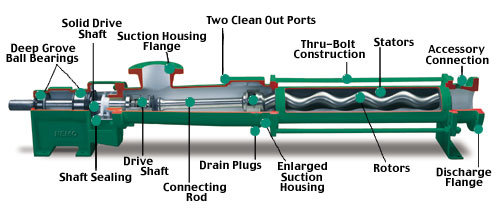
These pumps are recommended for materials that contain higher concentrations of suspended solids. They are commonly used to pump sludges. Progressive cavity pumps should NEVER be operated dry (without liquid in the cavities), nor should they be run against a closed discharge valve.
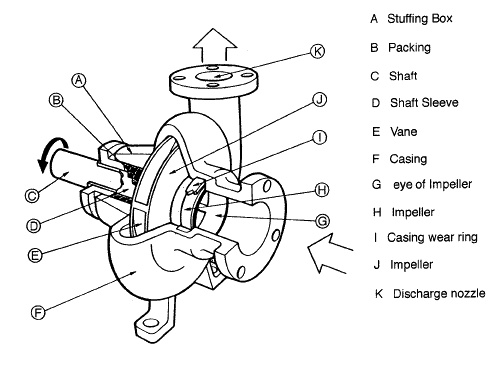
CENTRIFUGAL PUMP COMPONENTS
A centrifugal pump is constructed from about a dozen major components.
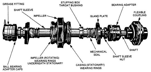
The impeller is attached to the pump shaft. The shaft must be straight and true so that it will not cause vibration when it rotates. The shaft should be protected from potential damage caused by the failure of other pump parts. A shaft sleeve is used to protect the shaft in the area where the shaft passes through the pump casing.
The rotating assembly must be supported as it spins in the pump. Bearings hold the spinning shaft in place. There are two types of anti-friction bearings normally found in centrifugal pumps. One type of bearing is designed to keep the shaft from wobbling from side-to-side as it spins. This side-to-side motion is referred to as radial movement. The bearings used to prevent radial movement of the shaft are called radial bearings. The most common variety of radial bearing is the standard ball-type roller bearing.
As the impeller spins, water entering the suction eye pushes against the top of the impeller exerting force in the same axis as the pump shaft. This is referred to as up thrust. The pressure developed inside the pump also pushes against the impeller in the opposite direction. This downward force is referred to as down thrust. Bearings designed to support the shaft against this type of force are called thrust bearings. The most common variety of thrust bearing is an angular contact ball bearing.
The rotating assembly is placed in a pump casing. Part of the pump casing is specially designed to collect and direct the flow of water as it enters and leaves the impeller. This part of the pump casing is called the volute.
The suction and discharge piping are attached to the pump casing. The suction piping will always be larger than the discharge piping. Suction piping is designed to bring water into the pump at 4 ft/sec in order to minimize the friction loss on the suction side of the pump. The discharge piping is designed to carry water away from the pump at 7 ft/sec.
There are several important aspects to suction piping installation. Horizontal runs of piping should slope upward toward the pump. Any reducers on the line should be horizontal across the top instead of tapered. A reducer that is flat on one side is known as an eccentric reducer. A reducer that is tapered on both sides is called a concentric reducer.
These installation features are used to prevent the formation of air pockets in the suction piping. Air trapped in the suction piping can create restriction of flow into the pump.