LUBRICATION
Pumps, motors, and drives should be oiled and greased in strict accordance with the recommendations of the manufacturer.
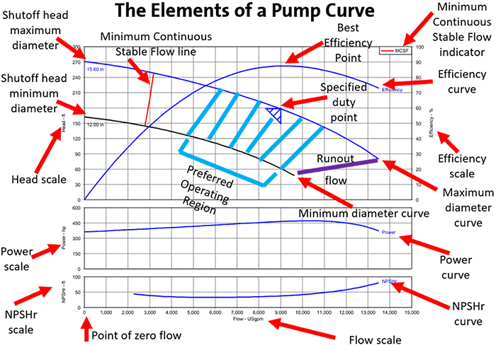
PUMP CHARACTERISTIC CURVES
Every pump has certain characteristics under which it will operate efficiently. These conditions can be illustrated with pump characteristic curves. The graph of the pump curve should show:
1. The head capacity curve
2. The brake horsepower curve
3. The efficiency curve
The graph may contain a curve labeled “NPSH” (Net Positive Suction Head) instead of a BHp (Brake Horsepower) curve. NPSH represents the minimum dynamic suction head that is required to keep the pump from cavitating.
To use the pump curve:
1. Start at the particular head pressure that is desired and then travel across the chart to the point where it crosses the head capacity curve (A).
2. Drop a straight line from this point down to the bottom of the chart to determine the gpm output at that particular head pressure.
3. The brake horsepower can be determined by tarting at the point where the vertical line crosses the horsepower curve (B) and going across to the right side of the chart. Use the same procedure for NSPH if it is used instead of BHp.
4. The efficiency of the pump at this flow and pressure is determined by starting at the point where the vertical line crosses the efficiency curve (C) and going over to the right side of the chart.
When the head pressure of the pump represented by this curve is 200 feet, the output is 350 gpm. The brake horsepower under these conditions is about 22 BHp and the efficiency is 80%. If the impeller or the speed of the pump changes, all of the pump’s characteristics will also change.
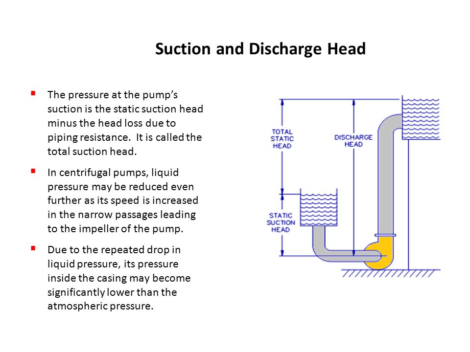
SHUT OFF HEAD
The highest head pressure that the pump will develop is called the “shut off head” of the pump. The shut off head for the pump in this curve is 240 feet of head. When a pump reaches shut off head, the flow from the drops to 0 gpm. This is a valuable piece of information for conducting a quick check of the pump’s performance. If the pump cannot generate its rated shut off head, the pump curve is no longer of any real value to the operator. A loss of shut off head is probably caused by an increase in recirculation inside the pump due to worn wear rings or worn impellers.
There is another factor that might affect the shut off head of the pump. The pump curve assumes that the pump is running at design speed. If a pump that is designed to spin at 1750 rpm and it is only turning at 1700 rpm, the shut off head will also be lower than the pump curve. However, if the pump speed is checked with a tachometer and found to be correct, the wear rings or impellers are probably in need of repair.
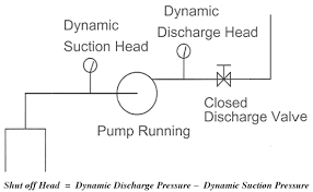
It is fairly easy to check the shut off head on a pump if it has suction and discharge pressure gauges.
1. Start the pump and close the discharge isolation valve. This will create a shut off head condition since the flow has been reduced to 0 gpm. The pump should not operate at shut off head for more than a minute or it will begin to overheat.
NOTE: NEVER attempt to create shut off head conditions on a multi-staged turbine well. The shut off head may be several hundred feet higher than normal operating pressure, which can cause damage to piping.
2. With the pump running at shut off head, read the suction and discharge pressure gauges. Subtract the suction pressure from the discharge pressure to get the shut off head. Compare the field readings to the pump curve to see if the wear rings are in need of replacement. If the shut off head matches the curve, the same calculation can be used when the pump is running normally, to estimate the Total Dynamic Head (TDH) and determine the flow when a meter is not available.